


![]()

Datasheet
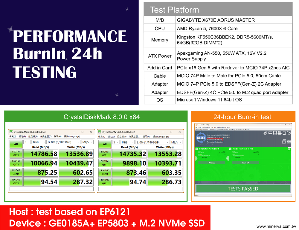
Test report
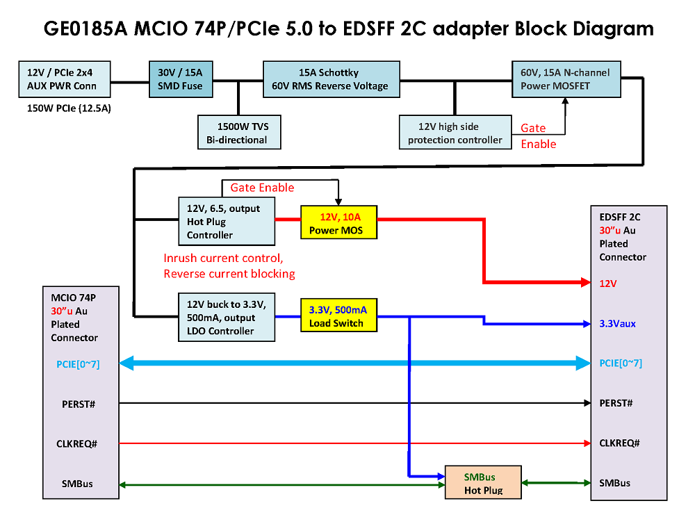
Block Diagram
2D drawing
![]()
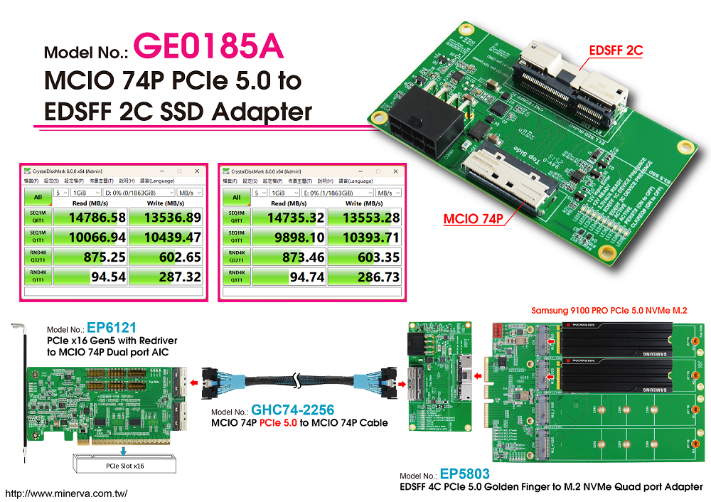
- MCIO(SFF-TA-1016) to EDSFF(Gen-Z) 2C convert for PCIe 5.0 signals
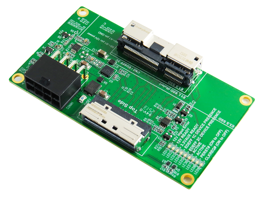
- Built-in MCIO 74P, 30u” Au Plated connector
- Built-in EDSFF(Gen-Z) 2C 30u” Au Plated connector
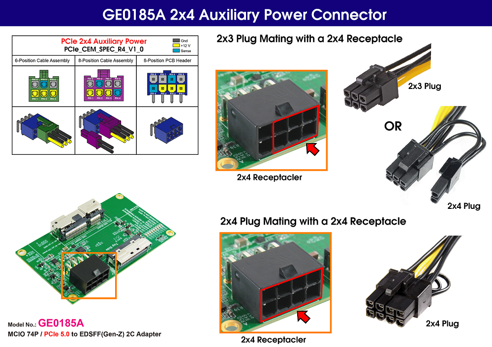
- 2x4 PCIe 12VAUX Power Input
- 12V Input power rail built-in 15A FUSE
- 12V Input power rail with 1500W Bidirectional TVS
- 12V Input power rail built-in 60V, 15A Schottky barrier rectifer
- 12V Input power rail high side controller with 60V, 15A Power NMOS FET
- Built-in 12V Hotswap Power controller with programmable Inrush Slew rate, support a maximun continuous current of 6.5A for EDSFF SSD protection
- Built-in 12V output with 30V, 10A N-Channel NexFET power MOSFET, 20m ohm with Reverse current protection
- 12V to 3.3V, 500mA LDO buck Power
- 3.3V, 500mA Load Switch
- LED1 RED LED on indicates 12V input Power Error
- LED2 Green LED on indicates 12V power ready
- LED3 Green LED on indicates 3.3Vaux power ready
- LED4 Green LED on indicates EDEFF 1C DEVICE PRESENC
- LED5 Green LED on indicates EDEFF 2C DEVICE PRESENC
- LED6 Green LED on indicates 3.3Vaux power ready
- LED7 Red LED indicates EDEFF Active
- LED8 Red LED indicates on to off for PCIe PERST# signals implementation
- LED9 Red LED indicates on to off for PCIe CLKREQ# signals implementation