

Datasheet

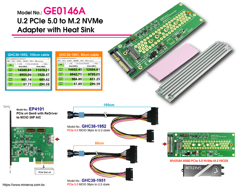
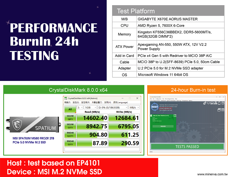
EP4101+GHC38-1951 Test report

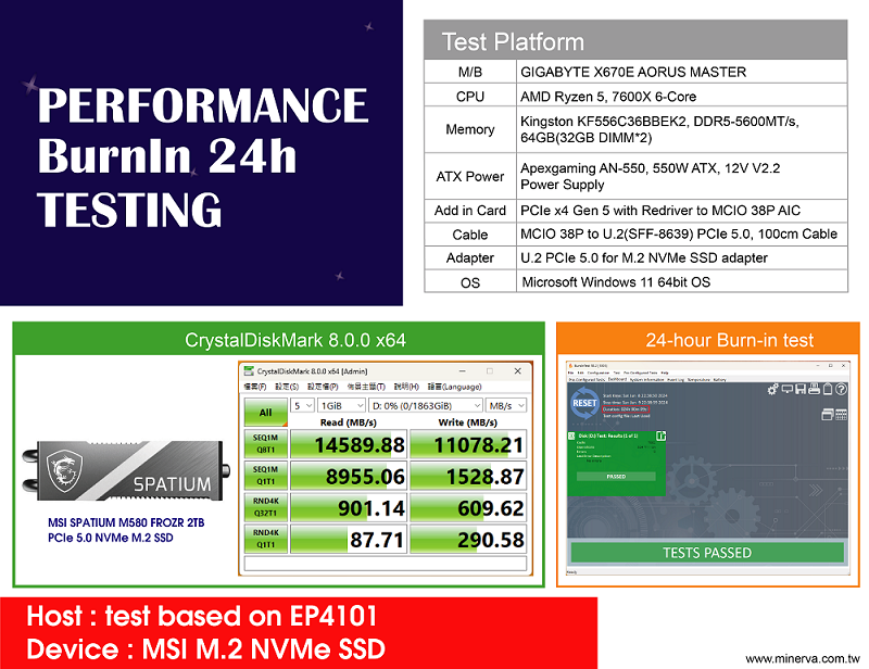
EP4101+GHC38-1952 Test report

GE0146A-2D drawing

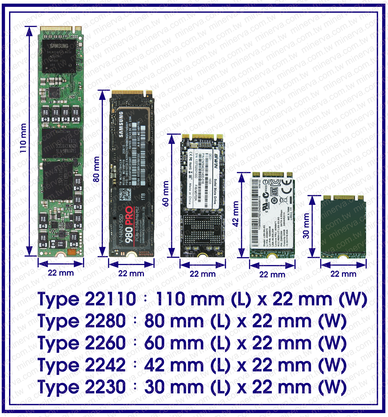
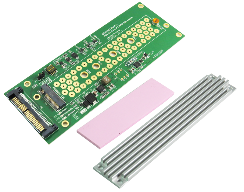
- M.2 NVMe to U.2(SFF-8639) convert
- Built-in SFF-8639 connector, pin-out defined by SFF-9402 Rev1.1
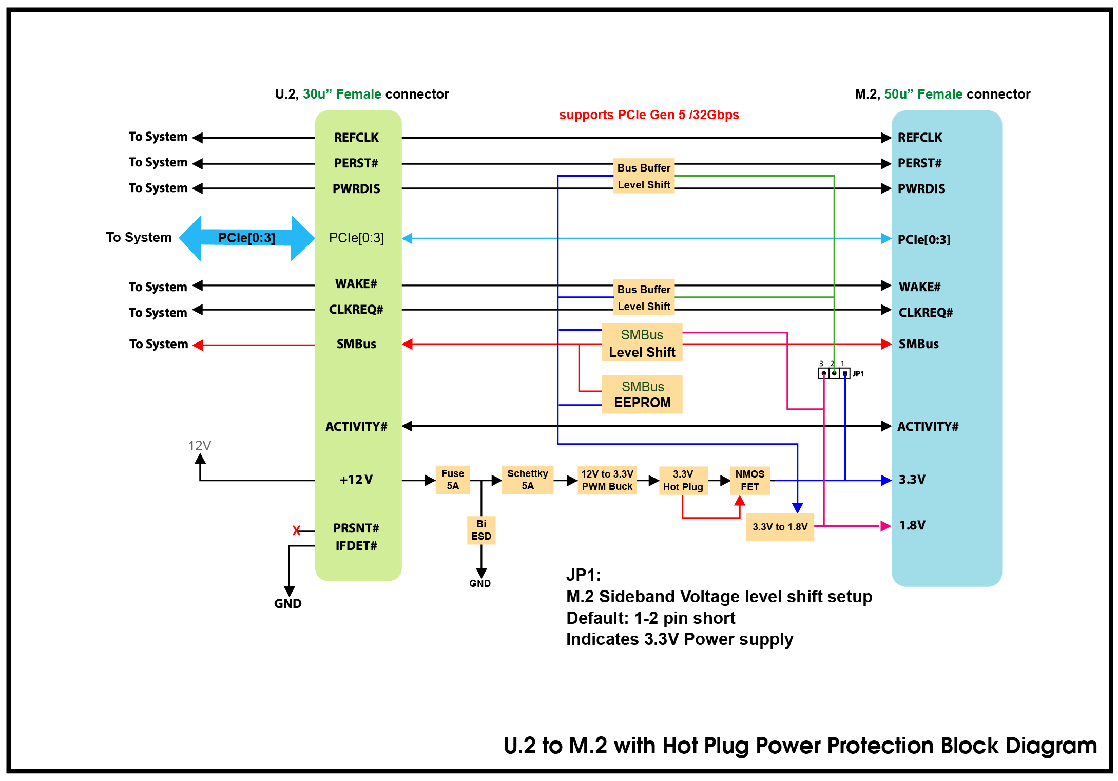
- 12V Input power rail built-in 5A FUSE
- 12V Input power rail with 400W Bidirectional TVS
- 12V Input power rail built-in 5A Schottky barrier rectifer
- PWM 12V to 3.3V synchronous buck converter Power for M.2 NVMe SSD
- ◆ 5.5A maximum output current
- ◆ Output Discharge Control
- ◆ The output overcurrent protection(OCP)
- ◆ Uundervoltage lock out protection(UVLO) monitor
- ◆ Over/Under Voltage Protection
- ◆ Thermal shutdown protection
- ◆ ESD HBM (Human Body Mode)/500V
- Built-in 3.3V Hotswap Power controller with programmable Inrush Slew rate, support a maximun continuous current of 6.5A for M.2 SSD protection
- Built-in 3.3V output with 30-V, N channel NexFET power MOSFET, 32m ohm with Reverse current protection
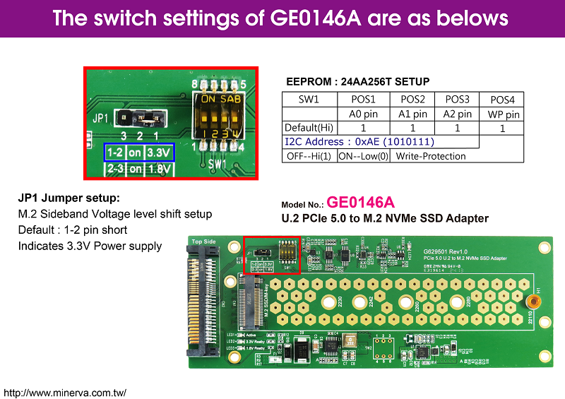
- Supports M.2 CLKREQ#, WAKE# Voltage level shift between 3.3V or 1.8V
- Supports M.2 /1.8V to U.2/3.3V SMBus Level Shift, isolated and repeater
- Built-in SMBUS EEPROM 64KB
- LED1 RED LED Blinking indicates M.2 active status
- LED2 Green LED on indicates 3.3V power ready
- LED3 Green LED on indicates 1.8V power ready
- LED4 Red LED indicates on to off for PCIe PERST# signals implementation

