


![]()

Datasheet
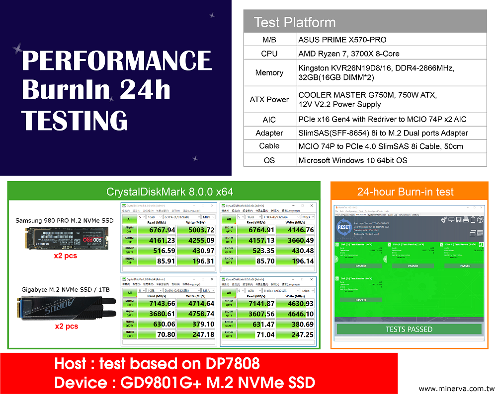
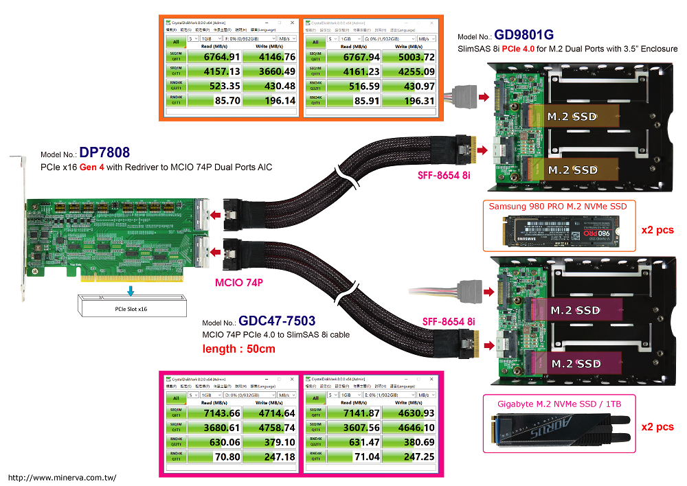
Test report for GDC47-7503+GD9801G
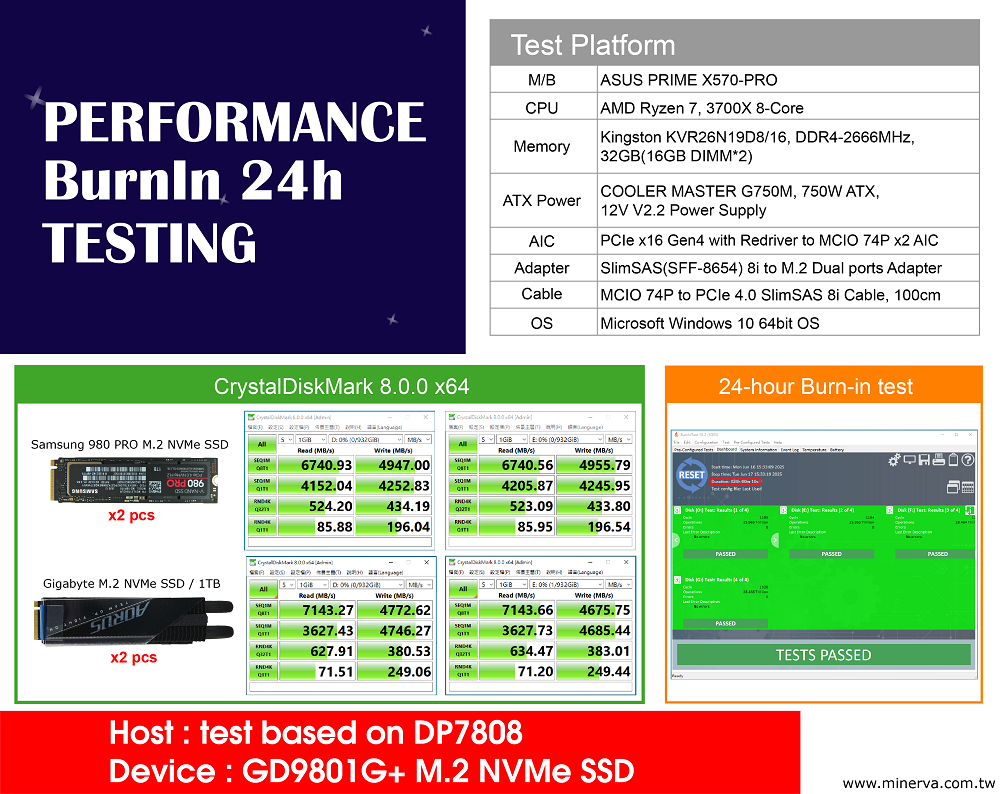
Test report for GDC47-7504+GD9801G
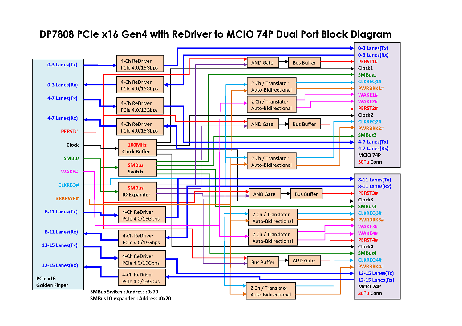
Block Diagram
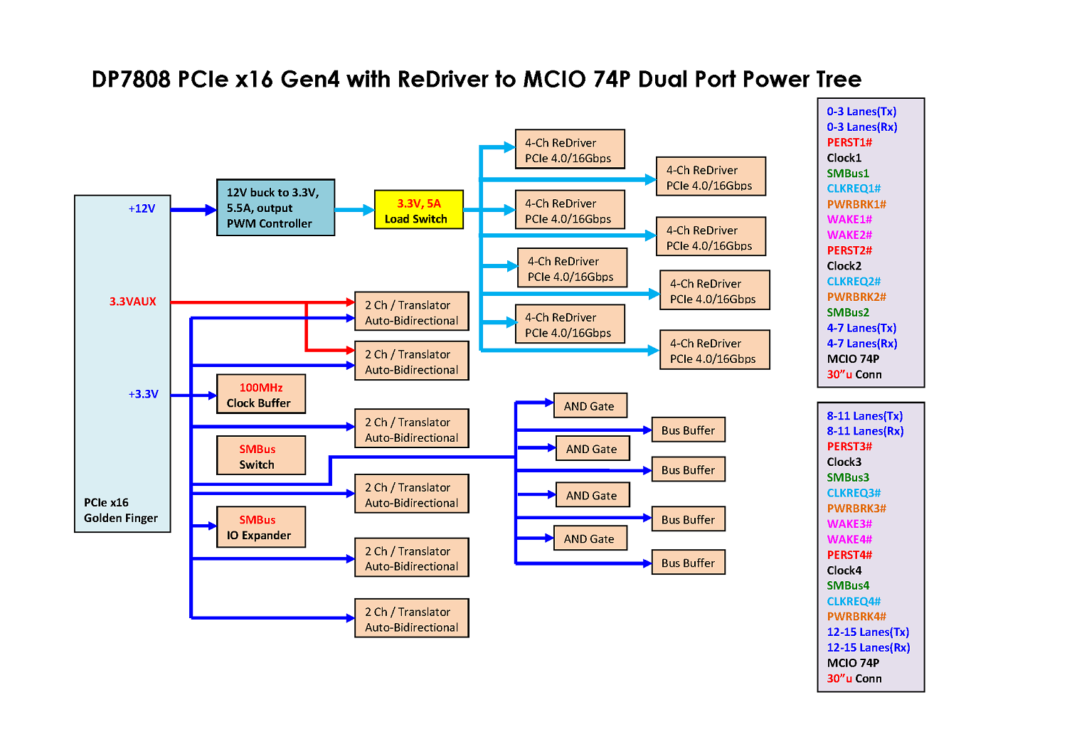
Power Tree
2D drawing
![]()
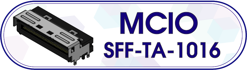
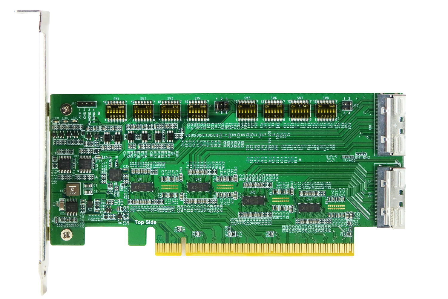
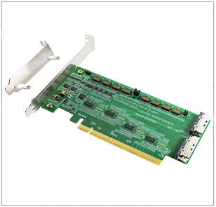
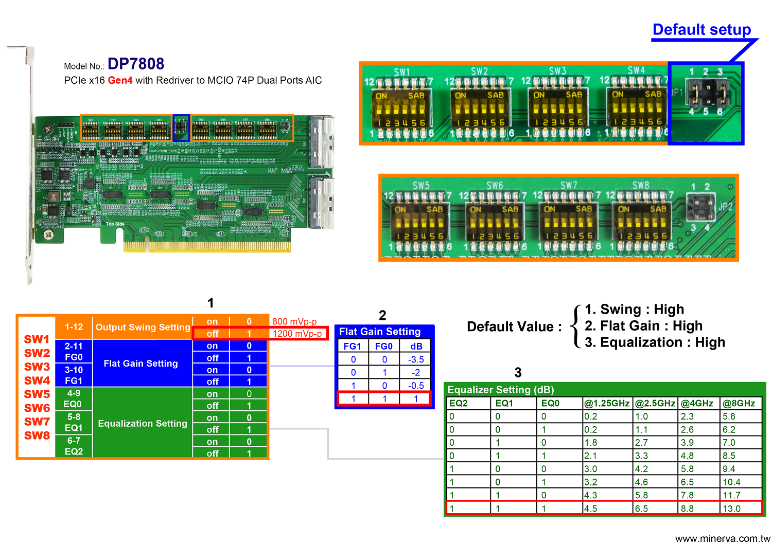
- MCIO 74P(SFF-TA-1016) to PCIe x16 Gen4 convert
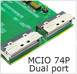
- Built-in MCIO 74P connector x2pcs
- Built-in ReDriver to extend PCIe 4.0, 16GT/s 16 lanes differential pair signals data link width.
- The PCIe 16 lanes can be bifurcated into four x4 link width to support different system topologies
- Built-in PCIe 100MHz Clock buffer(Address: 0x6C) for MCIO 74P(SFF-TA-1016) dual port to drive longer cable length
- Built-in SMBus Switch(Address: 0x70) with Reset Funtion for MCIO 74P(SFF-TA-1016) SMBus communication
- Built-in SMBus I/O Expander(Address: 0x20) for OOB(out of band) management to remote MCIO 74P(SFF-TA-1016) Reset signals.
- Supports PCIe PERST# management to control MCIO 74P(SFF-TA-1016) Reset signals.
- Built-in PERST# Bus Buffer to be used more cable length.
- Built-in WAKE# Auto-Bidirectional Bus Buffer to be used more cable length.
- Built-in CLKREQ# Auto-Bidirectional Bus Buffer to be used more cable length.
- Built-in PWRBRK# Bus Buffer to be used more cable length.
- Built-in 12V to 3.3V, 5.5A PWM Power controller
- Built-in 3.3V Power Load Switch for ReDriver controller Power Protection.
- The WAKE# signals power supply can choose +3.3V or 3.3VAUX, the default is 3.3VAUX
- LED1 Green LED on indicates AIC ready
- LED2 Red ON to OFF indicates PERST# Normal (Function intentionally inverted)
- LED3 Red ON to OFF indicates PERST# Normal (Function intentionally inverted)
- LED4 Red ON to OFF indicates PERST# Normal (Function intentionally inverted)

![]()