


![]()

Datasheet
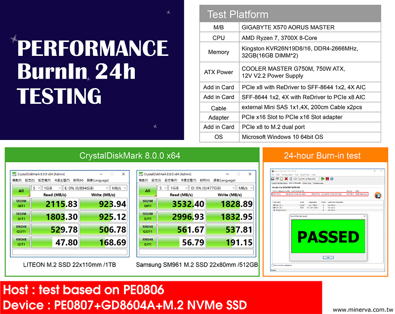
Test report
2D drawing
![]()
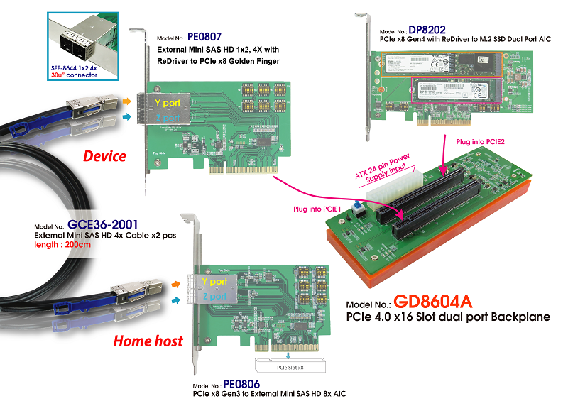
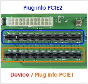
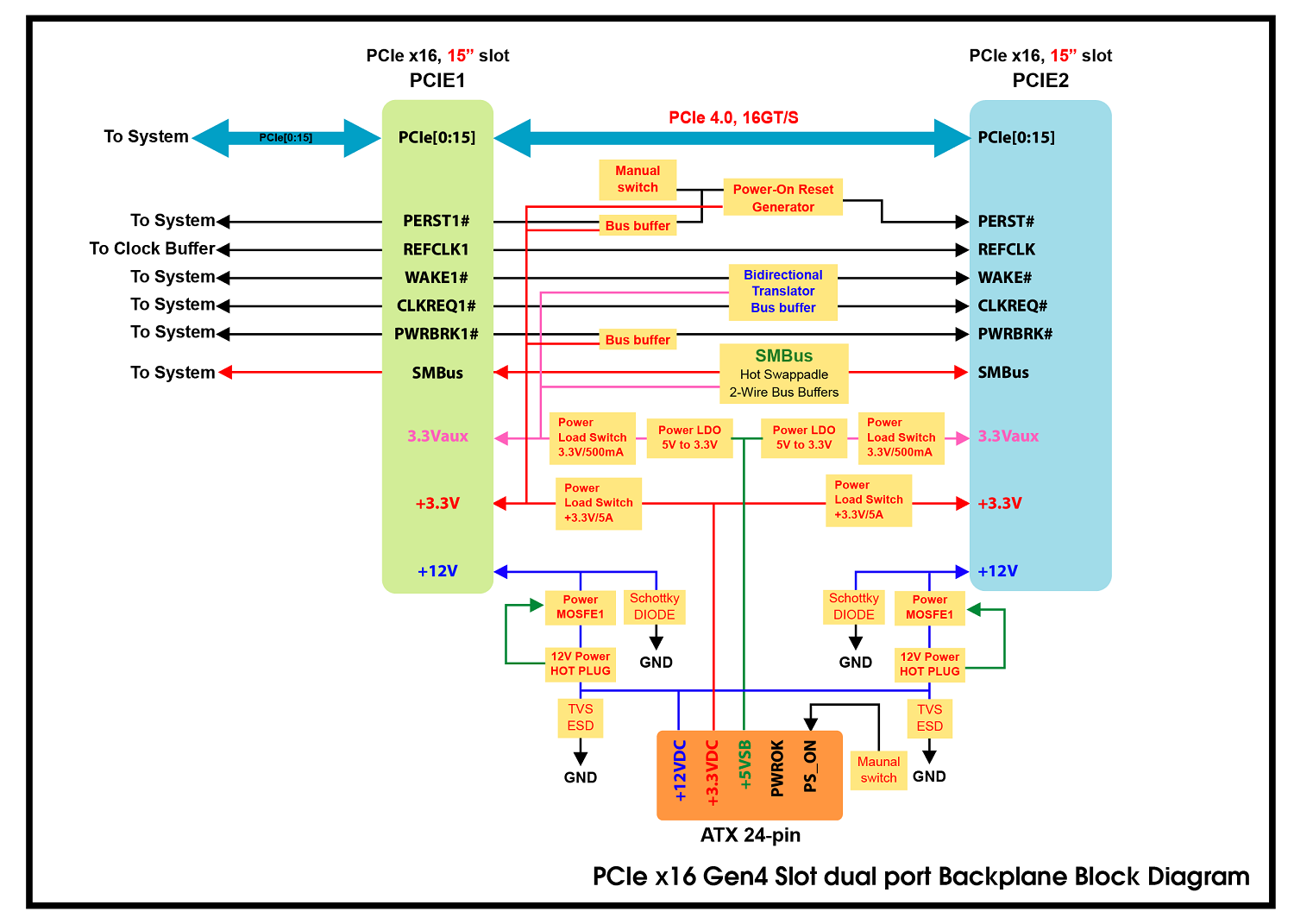
- PCIe x16 to PCIe x16 signals extension
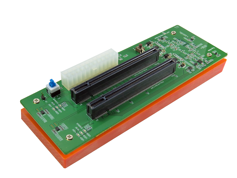
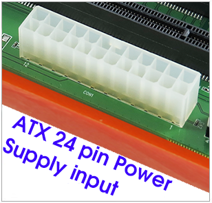
- Built-in ATX 24-pin Power supply input
- Built-in PCIe x16 with 15 microinches of gold on mating end Slot
- Built-in +12V Hot Plug Power with eFuse protection for PCIe +12V for each slot
- ◆ Programmable Current Limit: 6.5A
- ◆ Programmable Inrush Current Slew Rate
- ◆ Thermal shutdown protection and fault alert
- ◆ Back-to-Back (B2B) FET Operation
- PWM synchronous 12V to 3.3V buck converter Power for each slot
- ◆ 4A maximum output current
- ◆ Over Current Protection
- ◆ Under Voltage Protection
- ◆ Under voltage lock out protection (UVLO) monitors
- ◆ Thermal shutdown protection
- ◆ ESD Human Body Mode(HBM)/2KV
- Built-in 3.3V Power Load Switch for PCIe +3.3V
- 12V to 3.3V LDO buck converter Power for PCIe 3.3Vaux for each slot
- ◆ 500mA maximum output current
- ◆ Over Current Protection
- ◆ Thermal shutdown protection
- Built-in 3.3V Power Load Switch for PCIe 3.3Vaux
- Built-in SMBus Hot Swappable 2-Wire Bus Buffer
- Built-in PCIe WAKE# Bidirectional Translator Bus Buffer
- Built-in PCIe CLKREQ# Bidirectional Translator Bus Buffer
- Built-in PCIe PWRBRK# Bus Buffer
- LED1 Green On indicates PCIe +12V power ready for PCIE1 Slot
- LED2 Green On indicates PCIe +3.3V power ready for PCIE1 Slot
- LED3 Green On indicates PCIe 3.3Vaux power ready for PCIE1 Slot
- LED4 Green On indicates PCIe +12V power ready for PCIE2 Slot
- LED5 Green On indicates PCIe +3.3V power ready for PCIE2 Slot
- LED6 Green On indicates PCIe 3.3Vaux power ready for PCIE2 Slot
- LED7 Red On to OFF indicates PERST# Normal (Function intentionally inverted)
![]()
![]()